Introduction[]
The University of Minnesota Solar Vehicle Project has been building their chassis out of prefabricated composite panels since 1995, and over the course of 12 cars, has refined the process considerably. Although our box-beam chassis design is not particularly complex or exciting, it is extremely light and simple to construct. After attending NASC 2008 and ASC 2010, I noticed that there are several important aspects of our design and construction process that appear to be unique to our project. There's nothing particularly secret about our process (most of it can be told in pictures), so this document aims to present our process in a clear fashion, as well as provide some general guidelines for composite chassis design.
Although this page deals specifically with composite chassis design and construction, much of what is said here pertains to design in general (Test your materials, build a mockup, etc).
Feel free to ask questions/offer constructive criticism on the talk page. Other UMNSVP Members should feel free to revise this page. --- Adem Rudin, UMNSVP
Updated December 2015. JakeHerbers (talk) 21:30, December 18, 2015 (UTC)
Step One: Materials and Construction Technique Testing[]
The first step in building any composite structure should be to test your materials and construction techniques to failure. Note: Materials testing and validation is NOT AN OPTIONAL STEP for composite construction. Until you validate and understand all of the mechanical properties of the materials you are working with, you have no idea what appropriate loading parameters are and there is no way to safely proceed with design. If you do not have the resources, knowledge, or time to do extensive material testing, you should not be building a composite chassis.
When designing a structure that is composed of glued composite panels, is is crucial to know four values in particular:
- The bending strength of the panels (verify manufacturer specs)
- The maximum tensile force a glue joint can withstand per unit length
- The maximum bending moment a glue joint can withstand per unit length
- The pullout strength in sheer (in-plane forces) of the method of bolting brackets to panels
Note that Minnesota generally does NOT care about the pullout strength of bolts in the out-of-plane direction, because loading composite panels that way is stupid and you shouldn't do it. Why will be discussed later. If you do load panels this way, out-of-plane pullout is a CRITICAL value and should be tested as well.
You need to perform these tests to verify to yourself as well as to your team that you know what you are doing, and your chassis will not fail. The inspectors also love to hear that you have empirically tested your parts to failure.
The following diagram shows a standard "T-joint" between two panels. I'm sure you can dream up all sorts of brackets to hold the bottom panel in place while applying force in the vertical and horizontal direction to the upright panel, in order to perform tests #2 and 3.
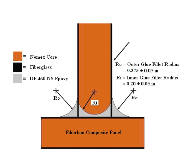
You will note in the above diagram that the radii of the glue fillets are called out. "Ri" is mostly a pipe dream, just get a healthy amount of glue in there. "Ro", on the other hand, can be closely controlled. A tongue depressor or spoon with the correct radius tip is run along the joint after the glue is laid down; pressing the glue into the corner, shaping the fillet, and removing excess glue in one stroke. Make heavy use of masking or painters tape to keep glue off of places it shouldn't go. Place long strips of the tape parallel to interior corners where you want to place a glue fillet, 3/8 to 1/2 in. offset from the corner. If you are diligent about tape masking the final product will look amazing and you will be glad you did so. The glue fillet provides the large majority of the strength of this T-joint, so take care to do the fillet properly. This method of gluing should be used to assemble the entire final chassis.
Glue selection is likely the most crucial choice to make in regards to tests #2 and 3. Many teams wrap fabric across joints like this for extra strength, and our team has done this on past cars (Notably Aurora 4 in 1999). However, with the correct glue, this extra (messy, weight-adding) process is unnecessary. We currently use a 3M dual-part adhesive called DP-460NS. When testing the maximum bending moment a glued T-joint can sustain, we delaminate the panels before glue failure occurs. When testing the maximum tensile strength of the glue joint, the panels either delaminate or fail in sheer before the glue fails. I do not recall offhand the actual strength, but the joints are certainly more than strong enough.
Performing test #4 is quite simple. Take a sample panel, and attach a bolt through the panel at either end. Using one bolt, hang the panel from something sturdy. Devise a method to suspend weight from the lower bolt. Add weight until the part fails. See below for how we tested our bolting method for our 2010 car, Centaurus 2:
")
")
")
Each of those buckets pictured is ~80lbs of sand. In the end, we stuck another bucket of sand onto either end of the 4x4, and then both myself and Sam hung off the ends. No failure was observed, and no creaking or cracking was heard. At this point, we had loaded 1130lbs onto the panel, and were at (or past) the load rating of the cheap chains, so we stopped. At a later date, one of our members took the panel to a fancy computerized tensile test machine, where the bolts ripped out of the panel at ~1600lbs of tension. Ideally, you would use an instrumented tensile test machine for the all tests listed above, but the pictures illustrate what can be done in an evening with cheap supplies that you may have on hand.
Do not use these values to design your chassis. Perform your own tests with YOUR panels, YOUR glue, YOUR grommets, YOUR assembly processes, etc.
Once you have your testing data, you can use that to calculate the required dimensions and specifications of your composite chassis. This guide from Hexcel is an incredible resource on failure modes and strength calculations of composite panels.
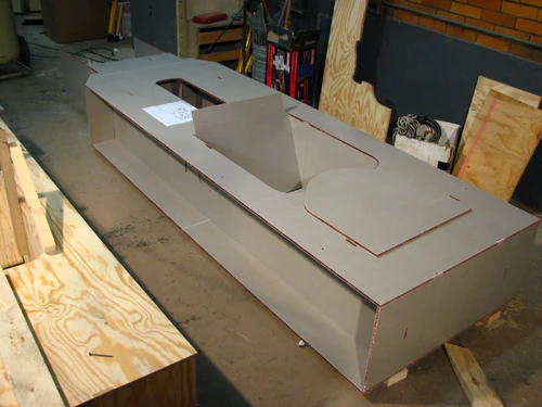
Step 2: Build a Full-Scale Mockup[]
No matter what kind of chassis you end up designing, you should always build a full-scale mock-up. You can use PVC to approximate a tube-frame chassis, and a chassis built out of flat composite panels is easy to mock up with plywood or OSB panels.
"Why build a mockup?" There's only so much you can do on a computer screen; CAD programs usually do a fairly poor job of giving you an idea of scale. Building a mockup will allow you to more easily figure out driver ergonomics concerns and driver egress, which both are of crucial importance. It'll also allow you to investigate rollcage dimensions, brake, accelerator, and steering attachment, etc.
You probably want to build at least two mockups. A preliminary one while the chassis design is still evolving allows you to test various configurations and alter them as needed. A duplicate of the final chassis lets you test the laser cutter or waterjet toolpath, as well provides a cheap, disposable chassis to test-fit parts on. Keep the duplicate of the final chassis around until the real car is driving; even if you think you're done with it, you'll find other things it's useful for.
Depending on how radically the chassis changes in the early stages of design, you may end up building multiple "preliminary" mockups.
")
")
")
Expand this section further?
Grommets[]
Some of you may have noticed that 1600lbs loading to failure number, up in the testing section. Yes, we could hang 3 of our solar cars (with drivers in them!) off a single bolt through a composite panel. The secret is the aluminum aircraft floor panel fasteners ("grommets") that we install into the panels.
")
")
These grommets are made by The YOUNG ENGINEERS, Inc. They are intended to be used with 100° countersunk AN bolts, although standard hex-head bolts can be used if a washer is placed between the head of the bolt and the countersink. TYE makes a wide variety of these grommets for different diameter bolts, with different diameter flanges, and for different panel thicknesses. Those pictured above are for a 3/16" bolt, have a 1" flange, and are for 0.5" thick panels. Minnesota has traditionally used TYE's aluminum grommets, however, they have recently come out with a line of Torlon plastic grommets that are supposedly lighter and just as strong. Minnesota used torlon grommets for their 2015 car and have not experienced any problems with them. ClickBond and Marketing Masters also makes a variety of grommets and spacer bushings, including ones with locking thread features, and ones made of torlon.
Almost all of the strength of the grommet comes from the glue that is used to attach the flange of the grommet to the face of the panel. To illustrate: for comparison, a panel identical to the one pictured (in the above section on testing) was prepared without gluing the grommets. The grommets pulled through the panel at approximately 150lbs! A stronger, heavier panel with more plys of fiberglass on either side failed before 500lbs without glue. The strength of the grommet will be roughly proportional to the sheer strength of the glue; you can estimate how much load a grommet will support by taking the rated sheer strength of your glue (usually in psi) and multiplying it by the bonding area on the flanges of the grommet.
This is a general procedure for installing grommets into composite panels. It is not necessarily a perfect set of instructions for each specific job. Read the entire list before starting. JakeHerbers (talk) 20:49, December 18, 2015 (UTC)
- Decide which grommets you want to install. I recommend a maximum 4 grommets per person per 1 hour session to make sure you finish before the glue cures.
- Use a couple of sacrificial test grommets and a bolt to ‘dry fit’ them into the chassis to make sure they fit.
- Do not force them together yet, they are a press-fit.
- If the bolt is not perpendicular to the panel that means the two chassis holes are not in line with each other.
- If the chassis needs to be modified, try to only file/ream the side of the panel away from the bracket or whatever is being bolted onto the grommet.
- Rough up the chassis panel with rough-grit sandpaper on both sides of the panel where the grommets will be glued. This provides more surface area for the glue to bond to.
- Wipe the sanded area off with isopropyl alcohol. This removes contaminants from the bond area.
- With test grommets in, put a piece of release tape over it and carefully cut out the circle of tape on the grommet, making sure to not cut the composite or leave any tape under the grommet flange.
- Determine what hardware you need to compress the grommets:
- Each grommet face must be compressed with a large washer or a metal bracket from the part that will attach to the grommets to ensure the entire flange bonds to the chassis.
- Select bolts, nuts, and washers to ensure that the grommet can be completely compressed, and that the nut does not ride up on the bolt’s grip length when you try to fully compress the grommet.
- Put blue release tape on any washers or brackets that will contact the grommet to avoid getting glue on them.
- Set out the hardware near their respective locations on the chassis panel
- Put on some latex gloves and set out all the grommets you want on a piece of cardboard.
- Aluminum grommets may be sanded with a rough-grit sand paper on the inside of the flange if you want to increase the bond area. Minnesota's 2015 torlon grommets came with a rough inner flange surface that did not (and should not) need to be sanded.
- Do not handle them with your bare fingers, the skin oils will contaminate the bond area.
- Get 1 male grommet and 1 female grommet for each chassis panel hole.
- Think about if you need any countersunk grommets.
- Never throw away a grommet unless it is structurally broken.
- Wipe them all off on the inner flange surface with isopropyl alcohol on a Q-tip, especially if you sanded them or touched them with bare skin.
- Get some glue (DP-460ns), make sure it’s not expired, put it in the gluezooka. Either dump a glob onto a surface covered in release tape, mix it up, and apply it to the grommet with a razor blade, or put a nozzle on and run some glue through it once to ensure it's fully mixed, then carefully squirt it onto the grommet flange. Make note of the exact time it was dispensed (from the tubes, not necessarily from the nozzle). DP-460ns has a 1 hour worklife and is fully cured in 24-48 hours. Do not dispense the glue until all prep work in the previous steps has been done.
- Put the sticky grommets into their respective chassis panel holes.
- Make sure any countersunk grommets are on the correct side of the panel.
- Put the male grommet in first, then the female.
- Squeeze them together with your gloved fingers, but don’t force them to press-fit yet.
- Put your designated hardware from step 2 onto the grommets and compress them.
- Don’t forget release tape.
- Tighten the nut/bolt combo with a wrench and ratchet.
- Tighten until it is ‘tight but not too tight’ it takes practice to get a feel for it.
- Check tightness by turning the bolt head with a wrench.
- If you overtighten it the composite panel may experience damage, could be minor or catastrophic. Be very careful.
- If you hear the chassis panel cracking, stop immediately, and loosen it a turn. It doesn’t sound quite the same as release tape crackling.
- Once they are tightened, remove the hardware to make sure the grommets got fully compressed against the chassis panel.
- Wipe off any excess glue with a paper towel and/or razor blade, then if the grommets are flush, put the hardware back on, with brackets if necessary.
- Do not work past the DP-460ns’ 1 hour work life. Don’t be afraid to abort the mission if it can’t be salvaged. You will really really want to avoid having to drill out bad grommets later.
- Clean up your work area. Store the grommets and DP-460ns in a secure location where that won’t get contaminated or used for unimportant stuff.
- Leave the hardware in and do not touch them for at least 24 hours. Do not load the grommets for at least 48 hours.
Composite Panels[]
Minnesota uses professionally manufactured composite panels for constructing the chassis, as they are far stronger and lighter than anything we have the capability to lay up ourselves. Over the years, we have used panels from ACP, Hexcel, and Teklam, utilizing panels faced with carbon and fiberglass, with 1 and 2 plys of fabric on either side, 0.4" thick and 0.5" thick panels... Basically, we use whatever we can get our hands on at the time we're building the car. Fiberglass is nice because it's non-conductive. Fiberglass is also cheap, and companies are more willing to donate it than carbon. On the other hand, fiberglass composite panels are heavier than equivalent strength carbon panels. Fiberglass doesn't have to be heavy, though; Centaurus 2 was an all-fiberglass car, weighed 389lbs without a driver, and had zero structural issues.
If you choose to manufacture your own panels, you MUST extensively test the material properties of the paneling. If your test data strength values are significantly different than what the manufacturer's spec sheet says, that is cause for concern. Approximate values for different types of composite panels can be found in the appendices of this document from Hexcel.
Cutting the panels[]
It's possible to cut composite panels with either a waterjet or laser cutter. Minnesota has used both processes in the past (I know Aurora 4's chassis was laser cut, while Borealis III, Centaurus 1, and Centaurus 2 were waterjet. If any UMNSVP alumni want to weight in on how other cars were made, feel free --- Adem Rudin, UMNSVP 08:58, August 14, 2010 (UTC)).
Figure out where you will be cutting your panels early, perhaps even before you order panels. The size of the cutting table may limit the size of the pieces that can be cut, which may affect the chassis design. Talk to the operator well in advance to figure out any potential pitfalls, and to make sure that you are prepared and don't waste their time when you show up to get stuff cut.
Laser Cutting[]
The SVP hasn't laser cut composite panels for at least a decade. As far as I know, this is mostly because we've got a great relationship with a place that will do waterjet cutting for free. Laser cutting composite panels will leave carbon deposits on the panels, so they must be carefully cleaned before being glued together
Waterjet Cutting[]
A waterjet is a tool capable of slicing into metal or other materials using a jet of water at high velocity and pressure, or a mixture of water and an abrasive substance, such as powdered garnet. Wikipedia has a very good article on the subject. These are things you should keep in mind about the process:
- Ask the operator about minimum spacing between parts on the panels, and know your tolerances before you show up. The looser your tolerances, the faster the parts can be cut out.
- The panels will be placed on a steel grid above the water tank. When the waterjet traverses over one of the steel members, energy from the jet will be reflected back up into the panel. This is bad. You should place ~3/4" of lumber between the composite panels and the steel grate. Your best bet is two sheets of 3/8" OSB. Avoid plywood if you can, plywood will warp when wet. OSB is non-directional, so it won't.
- While the entry cut (on the top side of the panel) will be clean, the exit won't. When the waterjet cuts through the top skin of the panel and hits the air gap in the middle, the jet expands. The exit cut (on the underside) will end up scalloped. Upload Pictures!
- The abrasive used in the waterjet will get everywhere. Rinse the panels off while they're still on the tank, and clean them thoroughly before applying glue.
- Example parameters:
- 10/30 combo (or 0.010 jewel and 0.030 focusing tube) with 0.375 to 0.500 lbs of 80 or 120 grit garnet per minute. NOTE: Kerf = 0.030
- They may not have a 10/30 combo and want to cut using a 14/43 or similar. Extra testing may be required to verify resulting tolerance of parts.
- 0.003” CAM tolerance
- External cutting perform at 60 ipm, Kerf = 0.030.
- Internal Square Slots cut at 15 ipm, Kerf = 0.030. Yes, they will “slightly” over-erode your tolerance but that is a good thing with regard to assembly.
- Internal Drops (removed for weight considerations) cut at 60 ipm, Kerf = 0.030.
- Internal Grommet holes will need to be undersized for subsequent reaming operation.
- Cut with a 10/30
- Define the Kerf as 0.010 or smaller to leave extra meat on the walls
- Practice on some test parts before they CAM up all the parts
- The exacting dimensions of the grommet demands careful waterjet, drilling, and reaming operations.
- The performance of each waterjet cutting machine will vary, however, I would recommend 10 ipm.
- Leave 0.25” between your parts in the layout.
- Ask your CAM guy which way to orient your panels.
- Pre-Test an IGS or STEP import early in the process.
- Cut and assemble a test part, include Grommet hole, Slot feature, and Tab feature(s).
- Assemble Test Part “BEFORE” Jet-Edge CAMs everything so they know what parameters to use.
- Verify that you are happy with the resulting size of the grommet holes for subsequent drilling and reaming operations.
- Offer to help them (bring materials, eye protections, hearing protection, gloves, OSB, donuts, etc…)
- The 5-axis test parts should be on a separate panel if possible.
- Recommend CAMing each individual 5X part with its own G54 to minimize the flatness error in the waterjet tank.
- CAMing the 5x parts is a pain the ass so do your best to help the CAM guy out as much as possible.
- Offer to remove all the debris (OSB and composite skeletons) after cutting is complete, and clean the machine after cutting is complete.
- Estimate a 2 hour per panel effort so 6 panels represents 12 hours of someone’s “very-expensive” waterjet machine time as well as an operator and CAM guy.
- Maximum 45-50 degree angle for 5-axis parts, depending on the machine
- At least 0.25" away from panel edges, preferably more. Especially avoid long cuts next to the edge, it causes a 'splash zone'
- Make sure all pieces in the layout are the same thickness and in the same plane.
- Bring 1 extra OSB panel for every 2-3 panels in the wooden layout, and 1:1 for the composite layout
Joining Panels[]
How to seam panels together if you need to make them longer (C2 chassis rails). This can be done by bracing the 2 panels together, with DP-460ns in between, and laying up over the seam. Laying up over fillets in interior corners is also an option.
Finish this section!
Weight and Balance[]
- Weight on Wheels more important for what we're doing that worrying about sprung/unsprung weight
make this section!
Basic Minnesota Design[]
The Minnesota chassis design is, in its purest form, a box beam with a wide flange on either side of the top and bottom panels. The chassis design inherently has high bending strength front-to-back, as well as high torsional rigidity, in a very light and simple to construct package. Minnesota's 2015 chassis deviated a bit from this design since we had a beefier cruiser-style aeroshell.

One feature of this design that we don't see often on other cars is the full, continuous top panel. The top panel is important for several reasons.
- The chassis needs some way to transfer the compressive loads between the front suspension members. If the top panel was not present, the vertical sides of the chassis would be crushed inward. There are many other ways to transfer these loads, but a composite panel is probably lighter than any steel or aluminum brace.
- The weight of the driver and battery need to be transferred to the wheels, this imposes a bending moment on the chassis. Much of this is carried as tensile and compressive forces in the top and bottom panels. If the top panel were deleted, much of this load would be transferred to the vertical panels of the chassis, which would have to be beefed up considerably. This would result in a net weight penalty versus a fully boxed design
- The flange on the top and bottom is necessary for properly attaching our suspension to the car, as will be explained further along.
First, however, we may as well mention the big disadvantage to the box design: Packaging the chassis within the aerodynamic shell of the car can be a thorny issue.
- For starters, the bottom of the car must largely be flat. This isn't a big issue for most of the shapes solar car teams are working with, and there are ways around it if you are creative.
- Another facet of the issue is the interaction with the top of the car. Clearly, the chassis has to be thick enough, top-to-bottom, for the driver to fit their feet inside and work a brake and accelerator pedal. Because of the continuous, flat top panel, the chassis has to be this thick for its entire length, which may present issues at the leading or trailing edge of the car. One possible solution is to make the top and and bottom panels not parallel to each other, building a wedge-shaped chassis.


Aurora 2's chassis was distinctly taller at the back and shorter at the front. This allowed for a more aerodynamic nose section. The driver was almost dead center in the car, so the extra chassis thickness there was not an issue. Aurora 2 had the 2nd lightest car at Sunrayce '95 (323lbs without batteries or driver) and won Electronic Data System's award for "Best use of Aerodynamics in Design". Aurora 2 finished Sunrayce '95 in 2nd place overall.
The easiest way to get around the issue of chassis thickness is to simply delete the top panel, figure out some other way to brace the front suspension, and live with the weight penalty of beefier vertical panels. Pretty much every team out there building a composite chassis goes and does this; we prefer to keep the top panel (see the next section for why) and deal with the packaging issues.
")
")
Note Calgary's steel truss between the upper A-arms and shock mounts. Because the tubes are braced together, they can use weaker tubes to achieve the same overall strength, likely making that piece lighter than if they had simply spaned three independent tubes across the chassis, as some teams have done in the past. Making this brace do double-duty as the steering rack mount is a nice touch. This is a very well engineered component.
Stanford simply placed a vertical panel between the front wheels to carry the load; light and simple. Note how the sides of the chassis become much shorter at the back of the car than at the driver's feet, this is roughly the profile of their shell. A chassis with a boxed, flat top like Minnesota's would not have fit inside their shell.
Utilizing the Chassis Flange for Proper Panel Loading[]
One thing that Minnesota always concentrates on is only putting in-plane forces on the panels, never out-of-plane. First and foremost, as we've mentioned before, the grommets we use are extremely solid when loaded in this manner. When loaded out-of-plane, the edge of the flange of the grommet is a stress concentrator of the face of the panel, and the pullout strength is greatly reduced. In addition, the composite panels are much stronger in tension and compression than they are in bending. The chassis flange allows us to install our front suspension in such a way that we are loading the panels almost entirely in-plane. While it's possible to safely load composite panels out-of-plane, the panels must be made much heavier.
Other than our first car, we have always used a double-A-arm suspension in the front. On earlier cars, both the upper and lower A-arms were attached to a welded aluminum subframe that was then bolted to the chassis.
")
")
")
You can see that the subframe is attached to the chassis on the bottom panel, vertical panel, and top panel. This ensures that the subframe can not experience force in a direction in which at least some of the grommets are being loaded in the right direction.
Although the subframes shown above are fairly simple to build, they require quite a bit of precision welding, and add some weight to the car. Since 2001, we have been using a lighter and simpler method of attaching the front suspension. The pictures below are from Centaurus II, the 2010 car, but Borealis I, II, and III, and Centaurus I use the same concept.
")
")
")
These are pictures of Centaurus 2's front suspension in various stages of construction.
- First, note the three white panels that the front suspension attaches to. All of the forces the front suspension applies to these panels are largely in-plane with the panels. If you look again at the picture of Stanford's car further up the page, you will notice that the side panels of the chassis are loaded in bending by the upper A-arm, which means that the panels must be much beefier to withstand the forces.
- Note how the suspension panels are glued to the main chassis. DP-460, like most adhesives, is strongest in sheer. Most of the strength in this situation comes from the bond to the top and bottom panels of the chassis, not to the side of the chassis.
- Also note the brackets for the lower A-arm: they are attached to both the bottom panel and side panel; no matter how the suspension is loaded, one set of attachment bolts are loaded in-plane with the panel they are attached to. This strategy of two-panel attachment should be followed with any part of the car that may experience forces from multiple directions: Suspension, roll cage, etc.
")
")
The rear suspension follows the same design principles of the front suspension, the brackets for the swing-arm pivots attach to two panels 90° apart, and the rear shock attaches in a manner similar to the front.
Other design considerations[]
- Roll cage mounting
- Array support, aeroshell support/bulkheads, etc.
- Cruiser practicality stuff:
- Ergonomics: leg room, seat integrations, etc.
- Storage space
- Sweet dashboard, other creature comforts
Failure[]
With any engineering exercise, failure is always an option. Composite chassis can be fussier about loading conditions than tube-frame chassis, and fail with a heart-wrenching crunching noise. This guide from Hexcel has a great description of all the possible failure modes of composite panels and how to calculate their strength for each mode. Fortunately, the UMNSVP has only had one major structural failure over the years (past members, feel free to correct me if I'm wrong. --- Adem Rudin, UMNSVP). The rear shock mount of Borealis II fractured the panels it was mounted to when the rear suspension bottomed out on the 4th day of ASC 2003. The team fabricated an aluminum bracket that transferred the load from the rear shock mount to the rearward rollcage supports, and went on to finish in 2nd place overall.
")
")
")
")
")
")